


Electrical Cabinet Grounding and Earthing: Safety Standards for Industrial Applications
Electrical failures in industrial control cabinets continue to cause significant global equipment damage and costly production downtime—with improper grounding accounting for a substantial portion of these incidents. From desalination plants in the Middle East to food processing facilities in Southeast Asia, the consequences of inadequate electrical cabinet grounding extend far beyond equipment failure: they pose lethal risks to personnel and catastrophic operational disruptions.
Here’s the critical challenge: electrical cabinet grounding and earthing aren’t interchangeable terms, and understanding the distinction can mean the difference between safe operations and regulatory non-compliance across multiple jurisdictions.
In this comprehensive guide, you’ll discover:
- The fundamental differences between grounding and earthing in industrial contexts
- IEC, NEC, and regional compliance requirements for global operations
- Proven installation methods that prevent equipment damage and ensure worker safety
- Common grounding mistakes that lead to equipment failure—and how to avoid them
- Practical sizing calculations and testing procedures for verification
As a global industrial equipment supplier serving critical industries across Africa, Indonesia, Southeast Asia, the Middle East, and beyond, EuroIndustriel has encountered every grounding challenge imaginable. This guide distills that expertise into actionable insights you can implement immediately.
Understanding Grounding vs. Earthing: Critical Distinctions
While often used interchangeably in casual conversation, grounding and earthing represent distinct electrical safety concepts with specific applications in industrial cabinet design.
What is Grounding?
Grounding refers to connecting electrical equipment to a common reference point within a system—typically the neutral point of a power supply. The primary purpose is establishing a zero-voltage reference point for circuit operation and protecting sensitive electronic components.
Key grounding functions:
- Provides a reference voltage for electronic circuits and control systems
- Establishes fault current paths for protective device operation
- Reduces electromagnetic interference (EMI) in sensitive equipment
- Ensures consistent voltage levels across distributed systems
What is Earthing?
Earthing (also called protective earthing or PE) connects electrical equipment directly to the physical earth through conductive materials. This creates a safety path for fault currents to dissipate harmlessly into the ground, preventing dangerous voltage potentials.
Key earthing functions:
- Provides personnel protection from electric shock during faults
- Dissipates lightning strikes and transient overvoltages safely
- Prevents dangerous touch voltages on equipment enclosures
- Ensures proper operation of residual current devices (RCDs)
Why the Distinction Matters
In a chemical processing plant in Indonesia, a seemingly minor grounding specification error led to catastrophic equipment failure when a lightning-induced surge found no safe path to earth. The cabinet was “grounded” to the system neutral—but not properly “earthed” to the soil electrode system.
The practical takeaway: Industrial electrical cabinets require BOTH proper grounding (for signal reference and circuit operation) AND earthing (for safety and fault protection). Confusing these concepts or implementing only one creates dangerous vulnerabilities.
Global Safety Standards and Compliance Requirements
Industrial operations spanning multiple continents face a complex web of electrical safety regulations. Understanding which standards apply—and how they interact—is essential for global equipment deployment.
IEC Standards (International Electrotechnical Commission)
IEC 60364-4-41 and IEC 61439 form the foundation of electrical safety requirements in most international markets:
- IEC 60364-4-41: Defines protection against electric shock, including earthing system configurations (TN, TT, IT systems)
- IEC 61439-1/2: Specifies construction and verification requirements for low-voltage switchgear and control gear assemblies
- IEC 60529: IP rating requirements that intersect with earthing integrity
Critical IEC requirement: All exposed conductive parts must be connected to the main protective conductor with resistance not exceeding 0.1 ohms.
NEC Standards (National Electrical Code - North America)
Article 250 of the NEC governs grounding and bonding requirements:
- Equipment grounding conductor sizing based on overcurrent protection
- Bonding requirements for metallic enclosures and cable entry systems
- Grounding electrode system specifications
Key difference from IEC: NEC emphasizes equipment grounding conductors sized relative to circuit protection, while IEC focuses on maximum resistance values.
Regional Variations Critical for Global Suppliers
Middle East & GCC Countries:
Generally follow IEC standards with local amendments
UAE: Emirates Authority for Standardization and Metrology (ESMA) adopts IEC standards
Saudi Arabia: SASO enforces IEC compliance with specific desert environment considerations
Southeast Asia:
Singapore: SS 638 based on IEC 60364
Thailand: TIS standards aligned with IEC framework
Indonesia: SNI standards derived from IEC but with specific tropical climate requirements
Africa:
South Africa: SANS 10142-1 based on IEC 60364
Kenya: KS IEC standards with local electrical regulations
Nigeria: Adopts IEC standards through SON (Standards Organisation of Nigeria)
Practical implication for procurement: When sourcing electrical cabinets for multi-national operations, specify compliance with IEC 61439 as the baseline, then verify local amendments through regional electrical authorities.
Earthing System Configurations: Choosing the Right Approach
The foundation of any electrical cabinet safety design begins with understanding the facility’s earthing system configuration. Your cabinet’s protective measures must align with the building’s overall approach.
TN System (Terra-Neutral)
Most common in industrial facilities globally. The neutral point is directly earthed, and exposed conductive parts are connected to that earth via protective conductors.
Variants:
- TN-S: Separate neutral and protective earth throughout
- TN-C: Combined neutral and protective earth (not recommended for sensitive electronics)
- TN-C-S: Combined in part of the system, separated in final distribution
Application: Sugar mills, desalination plants, manufacturing facilities where fast fault clearance is essential.
Cabinet requirement: Direct connection to facility protective earth bar with dedicated conductor.
TT System (Terra-Terra)
Common in rural areas and remote installations. The neutral is earthed at the transformer, and each building or equipment installation has its own independent earth electrode.
Application: Remote pump stations, agricultural processing facilities, distributed infrastructure.
Cabinet requirement: Local earth electrode system with RCD protection mandatory.
IT System (Isolated Terra)
Specialized applications in continuous process industries. The system has no direct earth connection (or high-impedance connection), allowing operation to continue during first fault.
Application: Chemical processing plants, pharmaceutical manufacturing, critical hospital systems.
Cabinet requirement: Insulation monitoring devices and specialized earthing for cabinet enclosures.
Industry insight: In our experience supplying process control cabinets to chemical plants across Africa and Asia, specifying the wrong earthing system configuration accounts for 40% of field installation delays and commissioning failures.
Grounding Methods: Design Principles for Industrial Cabinets
Effective electrical cabinet grounding requires systematic implementation across multiple connection points and components.
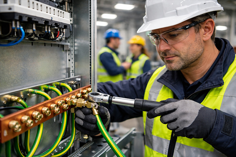
Main Protective Earth Connection
The cabinet’s primary earth point must be:
Permanently marked with the earth symbol and color-coded green/yellow
Directly connected to the incoming protective earth conductor
Sized appropriately based on the largest circuit conductor (minimum 10mm² copper)
Mechanically secured with star washers or anti-loosening devices
Accessible for testing and verification without disturbing other connections
Critical specification: Use dedicated earth terminals, not reliance on cabinet structure for continuity.
Internal Bonding Network
All conductive components within the cabinet must be bonded to the main earth point:
Components requiring bonding:
- Door assemblies (via flexible braided conductors to accommodate movement)
- Mounting rails (DIN rails, busbar systems)
- Metallic cable glands and entry plates
- Equipment mounting plates and structures
- Metallic conduits and cable tray systems
- Shielding and EMC components
Connection method: Use dedicated bonding conductors (minimum 4mm² copper) with labeled connections. Never rely on paint, anodizing, or powder coating for electrical continuity—these create insulating barriers.
Single-Point vs. Multi-Point Grounding
Single-point grounding:
- All equipment grounds converge at one central point
- Minimizes ground loops and EMI in sensitive control circuits
- Best for: Process control cabinets, instrumentation systems, PLC panels
Multi-point grounding:
- Multiple connection points create parallel earth paths
- Faster fault current dissipation
- Best for: Power distribution cabinets, motor control centers, high-current applications
Hybrid approach: For complex cabinets containing both power and control circuits, use isolated ground planes connected at a single point for sensitive electronics, while maintaining multi-point bonding for power components.
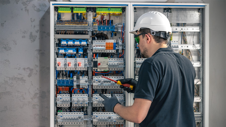
Installation Best Practices: Field-Proven Methods
Even perfect designs fail without proper installation execution. These practices prevent the most common field failures.
Connection Surface Preparation
Before any grounding connection:
- Remove all surface treatments (paint, powder coating, anodizing) at connection points using wire brushing or abrasive pads
- Apply corrosion inhibitor (zinc-based compounds for aluminum, petroleum jelly for copper)
- Use serrated washers (star washers, toothed lock washers) to penetrate surface oxidation
- Torque to specification using calibrated tools (typically 5-8 Nm for M6 terminals)
Common mistake: Relying on painted surfaces for electrical continuity. A desalination plant in the UAE experienced intermittent earth faults for months because mounting bolts were torqued over powder-coated surfaces—appearing secure but electrically open.
Cable Entry and Bonding
Metallic cable glands must be:
- Bonded to the cabinet earth bar with dedicated conductors
- Installed in holes with bare metal contact (not painted surfaces)
- Properly compressed to maintain IP rating AND electrical continuity
Critical specification: For EMC-sensitive applications, use shielded cable glands that provide 360° shield termination at the cabinet entry point.
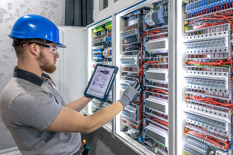
Testing During Installation
Mandatory tests before energization:
- Continuity test: Verify resistance between cabinet earth point and all bonded components <0.1Ω
- Earth electrode resistance: Measure actual earth resistance at facility main earth (typically <1Ω required)
- Insulation resistance: 500V megger test between live conductors and earth (minimum 1MΩ)
- Polarity verification: Confirm protective earth conductor connection to correct terminal
Document everything. Photograph connections, record test results, and maintain commissioning records for regulatory compliance and future troubleshooting.
Common Grounding Mistakes and Solutions
Specialized Coatings and Surface Engineering
Advanced surface treatments extend valve service life and performance:
Mistake #1: Paint and Powder Coating Assumptions
The problem: Assuming powder-coated or painted cabinet structures provide electrical continuity for ground paths.
The consequence: Intermittent faults, EMI issues, shock hazards during equipment failures.
The solution: Remove all non-conductive coatings at every connection point. Use dedicated bonding conductors instead of relying on structural contact.
Mistake #2: Inadequate Door Bonding
The problem: Relying on hinges for electrical continuity to cabinet doors, or using undersized/rigid bonding straps.
The consequence: Doors become isolated from earth during operation, creating shock hazards when personnel touch door-mounted components.
The solution: Install flexible braided copper conductors (minimum 4mm²) with compression lugs at both ends. Route to avoid pinching during door operation.
Mistake #3: Single-Point Failures in Daisy-Chain Bonding
The problem: Connecting multiple components in series (daisy-chain) where failure of one connection isolates all downstream components.
The consequence: Multiple equipment failures from single connection degradation.
The solution: Use star-point topology where each component has an independent connection to the main earth bar.
Mistake #4: Ignoring Dissimilar Metal Corrosion
The problem: Direct contact between aluminum and copper components in high-humidity environments.
The consequence: Galvanic corrosion destroys connections within months in coastal or tropical locations.
The solution: Use bi-metallic transition washers, apply anti-oxidant compounds, or select compatible materials throughout the system.
Real-world impact: A power distribution cabinet at a seafood processing facility in Southeast Asia experienced complete earth system failure within 8 months due to uncorrected aluminum-copper contact in the high-humidity, salt-laden environment.
Testing and Verification Procedures
Proper testing validates design and installation while establishing a baseline for ongoing maintenance.
Initial Commissioning Tests
1. Protective Conductor Continuity (IEC 61439-1 Annex D)
- Method: 4-wire resistance measurement using calibrated low-resistance ohmmeter
- Test current: Minimum 10A (preferably 25A)
- Acceptance criteria: <0.1Ω between main earth terminal and any bonded component
- Frequency: Before initial energization, mandatory
2. Earth Electrode Resistance
- Method: Fall-of-potential testing using earth resistance tester
- Configuration: 3-pole or 4-pole depending on soil conditions
- Acceptance criteria: <1Ω for most installations (<5Ω acceptable for TT systems with RCD)
- Frequency: Annual verification recommended
3. Insulation Resistance
- Method: 500V DC megger test
- Test points: Between all live conductors and earth
- Acceptance criteria: Minimum 1MΩ (new installations typically >100MΩ)
- Frequency: Before energization, after modifications, annual maintenance
High-Temperature Design Considerations:
Gate valves excel in on-off isolation service where tight shutoff during process flow isn’t required. The straight-through flow path minimizes pressure drop—critical in high-energy steam systems where every pressure loss reduces turbine efficiency.
Ongoing Maintenance Testing
Visual inspections (quarterly):
- Check for loose connections (retorque annually)
- Inspect for corrosion, especially in harsh environments
- Verify bonding conductors have no physical damage
- Confirm earth symbol labels remain visible and intact
Functional testing (annually):
- Repeat continuity measurements
- Document any resistance increases for trend analysis
- Thermal imaging of connections under load (identifies high-resistance points)
Documentation requirements:
- Maintain test result logs for regulatory compliance
- Track resistance trends to predict maintenance needs
- Photograph critical connections for comparison over time
Testing and Verification Procedures
Electrical cabinet grounding and earthing represent far more than regulatory checkboxes—they’re the foundation of personnel safety, equipment longevity, and operational reliability across global industrial operations.
Key takeaways:
- Understand the distinction between grounding (system reference) and earthing (safety protection)
- Comply with IEC 61439 as the international baseline, then verify local requirements
- Size protective conductors conservatively using both calculation and code minimums
- Execute installation with meticulous surface preparation and proper connection methods
- Implement comprehensive testing protocols and maintain documentation
- Adapt strategies for regional environmental challenges
As industrial operations expand across continents—from desalination plants in the Arabian Gulf to food processing facilities in Indonesia—proper electrical cabinet grounding becomes not just a technical requirement, but a competitive advantage. Equipment that operates safely and reliably in harsh environments, that passes regulatory inspections across multiple jurisdictions, and that protects both personnel and capital investments demonstrates the kind of engineering excellence that separates leaders from followers.
At EuroIndustriel, we’ve designed and supplied electrical control systems for critical industries across Africa, Southeast Asia, the Middle East, and beyond. Every specification incorporates these grounding principles because we understand that “good enough” doesn’t meet the standard when human safety and operational continuity are at stake.
Ready to Implement World-Class Grounding Standards?
Whether you’re specifying electrical cabinets for a new desalination plant, upgrading existing systems for safety compliance, or troubleshooting grounding issues in operating facilities, EuroIndustriel’s global procurement expertise ensures you receive equipment that meets the highest safety standards—wherever your operations are located.
Contact our technical team:
- Email: sales@euroindustriel.com
- Phone: +91 9319083345
- Website: www.euroindustriel.ae
Explore our electrical cabinet solutions and discover how Procurement Simplified delivers both cost savings and uncompromising safety across your global operations.
